Common Plastic Injection Molding Defects

1. Silver Marks / Surface Streaks
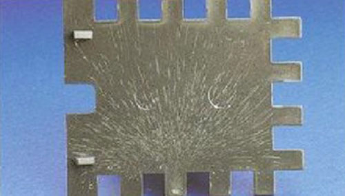
Silver Marks / Surface Streaks

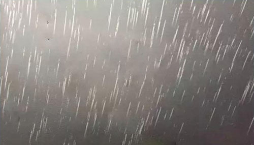
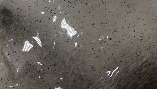
The process of injecting molten plastic into a mold is known as injection molding. The desired texture of the cavity steel is picked up by the molten plastic and imitated on the part. The temperature at which plastic melts varies depending on the base polymer being molded, from 176 °C to as high as 399 °C. Water turns to steam at these temperatures, and some low-molecular-weight additives may burn and produce volatiles. The speed at which the plastic is injected into the mold will shear the molecules as well. The molecules may deteriorate under excessive shear. The plastic then flows into the mold along with steam and volatiles (hereafter collectively referred to as volatiles) from degradation. The volatiles reach the surface and prevent the molten plastic from coming into contact with the mold steel while also spreading the volatile on the interface of the melt and the mold steel due to the fountain flow of the plastic into the mold cavities. This manifests as streaks and is referred to as splay. Splay is a different name for Silver streaks.

Silver stains degrade the mechanical strength of plastic components in addition to their appearance. The gases in the plastic part's melt surface are primarily to blame for the formation of the silver marks. We can learn how to address the flaws by identifying the source of these gases.

Sources of defect:

Material/ Granulate:

  • Residual moisture in the granulate too high
  • Packaging defect of the granulate
  • Additives are moisture-sensitive (soot)

Plasticising:

  • Back pressure too low
  • Decompression path too big
  • Gas content too high
  • Dosing speed too low
  • Dosing volume too low
  • Melt temperature too low
  • Pre-drying temperature too low / time too short
  • Feed line/hoper part too cold

Cooling:

  • Mould temperature too low (cold)

Injection:

  • Injection speed too low

Mould:

  • Mould leaking (cooling hole fissure)
  • Flow cross-section too small
  • Insufficient ventilation

Machine:

  • Hopper is not covered
  • No shut-off nozzle
  • Dryer defect (in need of maintenance)
  • Dryer too small
  • Feed route for the material too long
  • Use of 3- zone screw

2. Welding Line

Welding Line

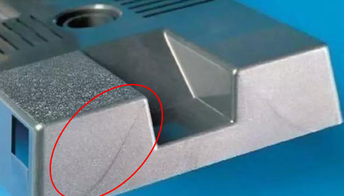
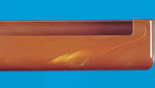
Small lines called welding lines are produced in the region where two or more melt plastic fronts from the material flow collide. If the fronts don’t bond well, indentations will occur. These indentations are often visible as visual defects. However, even when not visible they are a weak point in the material structure and thus have a lower strength.

The fine lines can appear on both the front and back sides of a finished product due to insufficient fusion. The multi-gate injection molded products are where we typically see the welding lines we discuss. These lines frequently resemble the joining of two plastic planes when the part has fully solidified. This problem is typically brought on by different mold temperatures or by melt temperature that is too low. Most often, these lines can be seen on large-sized products and cannot be completely eliminated, but only reduced or moved to another place on the part. When using color mixtures, they can also appear.

Most often, this line appears on the opposite side of the part fill inlet.

Sources of defect:

Material:

  • The plastic material isn’t fully melted or is under- drying
  • The material isn’t pure or contaminated with Impurities
  • There is too much mold release

Mould:

  • The mold temperature is too low
  • The gate is too small or the location of gate isn’t suitable
  • The main runner and sub-runner are too thin or too long
  • There is excess air inside the mold

Holding pressure:

  • Holding pressure too low
  • Packaging defect of the granulate
  • Additives are moisture-sensitive (soot)

Plasticising:

  • Melt temperature too low
  • Different wall thicknesses

Cooling:

  • Mould temperature too low (cold)
  • Mould wall temperature too low in the area of the weld line
  • Hot runner temperature too low

Injection:

  • Injection speed too high at the end of the flow path (air can not escape)
  • Injection speed too low
  • The injection pressure is too low
  • The cold-slug well is too small

3. Splay Marks

Splay Marks

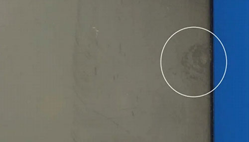
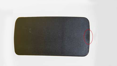
After the part is formed, the splay mark, which resembles water waves, cannot be removed. Mostly plastic components with a smooth finish exhibit it. Splay marks are brought on by the first melt cooling too quickly while being pushed forward by the hot, melted plastic, which results in the formation of water wave lines. By raising the melt temperature and mold temperature, quickening injection speed, and lengthening hold-in times, they can be eliminated. Water ripple formations will also result from the direct entry of the cold material still at the nozzle's front end into the mold cavity. To effectively prevent the occurrence of the splay mark, a cold material well should be opened at the end of the main channel.

Sources of defect:

Material:

  • Poor melting and plasticization of raw materials
  • The poor fluidity of melting material
  • Mold temperature or material temperature is too low

Plasticising:

  • Slow injection speed at the splay mark
  • The cold material well is too small or insufficient
  • Pressure too low or time too short

Mould:

  • The gate is too small or at an inappropriate position
  • The flow channel is too long or too fine (melting prematurely cools down)

4. Air Bubbles

Air Bubbles

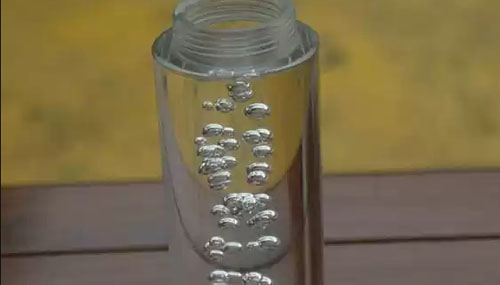
These are the holes made inside a finished product's thick wall. When a product is opaque, the bubbles cannot be seen from the outside; we must cut the product open to see the bubbles. Since the thick wall's centre cools most slowly, the surface's quick cooling and rapid shrinking will pull the raw material, resulting in air pockets and vacuum voids. Vacuum voids are created, giving the product a poor appearance that is typically most noticeable on transparent items. These items are most frequently seen on electronic goods, such as transparent lenses and transparent optical items.

Of course, it is still possible to increase wall thickness control while keeping the range under your control during design. For instance, when a product's overall thickness is too thick, that is, greater than 5mm, air bubbles are more likely to form.

When the mold cavity is fully filled, it is possible that the plastic is flowing too quickly and that the mold can't release the air quickly enough. In the materials, this can cause bubbles to form. Both very big and very small ones are possible. This problem differs from vacuum voids in the presence of air due to a similar but not identical set of causes. By heating the affected area with a heat gun or a lighter to see whether the plastic gets sucked in or pops, you can determine whether the flaw is a bubble or a vacuum void. A bubble with air trapped in it would pop, while a vacuum void would sink, causing a depression due to environment pressure.

Causes of Bubbles

Trapped Air

If a large amount of air is involved in the metering process, it is easy to generate a bubble. Specifically, it is easy to cause a bubble when the screw speed is fast, the back pressure is low, and the injection volume is large. In addition, during the cavity filling process, some flow patterns sometimes also cause air to be trapped in, creating a bub.

A large amount of gas is generated in the resin

The bubble is also easily caused by a large amount of gas generated in the resin. When the temperature of the barrel is too high and the residence time is too long, the generated gas will increase, and the bubble is thus easily generated. In addition, when there is insufficient drying and too much moisture is contained in the material, the bubble is also generated.

Sources of defect:

Material/ Granulate

  • Raw materials are not fully dried
  • Material with high viscosity
  • Different granulated size (regrind material)

Plasticising:

  • Back pressure is low or the melt temperature is too high
  • Decompression distance too long
  • Decompression speed too high
  • The screw rotation speed or the injection is too fast

Injection:

  • Injection speed too High

Mould:

  • Incorrect gate size – decrease or different shape
  • Nozzle hole is too small
  • Nozzle does not seal correctly on sprue bush
  • Mold temperature is too low
  • The gas can’t be expelled quickly enough
  • Insufficient venting in the mold
  • Significant changes of the flow cross-section > part design
  • Sharp corners and edges > part design

5. Warpage

Warpage

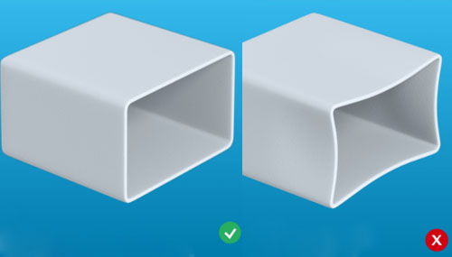
Uneven shrinkage results in warping, which is a change in the shape of the component. In general, shrinkage is influenced by the plastic's structure, but it is also influenced by fillers, materials used as reinforcement (like glass), and orientation ratios.

The resin in the mold is put under a lot of pressure during injection to create internal stress. Shrinkage also varies sectionally in the part because the pressure and cooling conditions during the injection moulding process are very different sectionally and the material frequently exhibits anisotropic shrinkage behavior.

Deformation of the finished product after mold release is visible on both sides, and it most frequently occurs on thin-walled products.

Warpage is obviously simple to check out. It typically occurs most frequently on very long, thin plastic products. To solve this issue, it is only necessary to add ribs or thicken the product's wall at the time of design.

Sources of defect:

Material/ Granulate

  • Shrinkage behaviour (lengthwise – crosswise too different). Plastic shrinkage anisotropy is too high (tendency to react to pressures from different directions
  • Temperature in the annealing furnace/painting line too high

Plasticising:

  • Melt temperature incorrectly selected
  • Incorrectly selected holding pressure (no holding pressure profile used)
  • The injection pressure or holding pressure is too high
  • The finished product has not been cooled and set when it is taken out of the mold
  • The packing is too dense, forming internal stress
  • Insufficient injection volume leads to shrinkage and deformation

Cooling:

  • Cooling time too short

Injection:

  • Injection speed incorrectly selected
  • Changeover point incorrectly selected

Mould:

  • Closing force too low
  • Gate too small or not balanced, no sufficient holding pressure time possible
  • Uneven holding pressure effect with several gates
  • Sectionally different shrinkage on the component
  • Different solidification conditions due to uneven mould wall temperatures lead to sectionally different shrinkage
  • The front and back mold temperature is not adaptable, the temperature difference is large or unreasonable
  • The plastic parts stick to the mold
  • Uneven wall thicknesses - (Part design problem)
  • Parts too warmly packed - (Storage / packaging problem)
  • The shape and thickness of the finished product is asymmetric
  • The ejection system is unbalanced

Machine:

  • Uneven locking force due to the bar wear
  • Inaccurate control of the injection speed

Peripherals:

  • Flow rate too low
  • Filter calcified and/or dirty

6. Flow Marks

Flow Marks

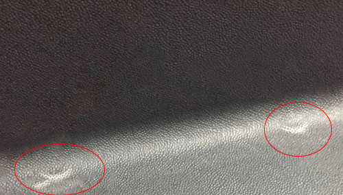
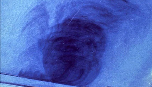
A fine wavy pattern in the form of a tree ring around the gate appears on the surface of a finished product when the melt plastic material is flowing in the tool cavity. This is what we typically mean by the swirl marks, which extend outward from the gate and are most noticeable on matte-textured products.

It is the most challenging problem to solve or modify in terms of a product's appearance. In order to lessen the problem, the majority of mold factories demand that the gate be designed on the outside of a product.

Sources of defect:

Material/ Granulate

  • Material with high viscosity
  • Size of littering unfavourably designed

Plasticising:

  • Melt temperature too low

Cooling:

  • Mold temperature is too low or varies greatly

Injection:

  • Injection speed in critical range too low / high

Mould:

  • The product is too thick while the gate is small – (part design)
  • Sudden changes in wall thicknesses are too great – (part design)
  • Different surface structures on opposite walls
  • Cooling partially insufficient
  • Cooling added
  • Insufficient venting in the mould

Peripherals:

  • Temperature control units with different capacities in use
  • Filter of the Temperature control unit calcified and/or dirty

7. Short Shot

Short Shot

"Short shots" in injection molding happen when the injected molten plastic material solidifies inside the mould before filling the cavity of the mould. The lack of melt or material or too low of an injection pressure is typically to blame for the finished product not being fully filled or having a part missing. The defect frequently manifests itself at the same location on the component or when the mold filling is changed from cycle to cycle. Additionally, multiple cavities tools frequently occur.

During mold design, the "short shots" flaw can be improved.

Sources of defect:

Material/ Granulate

  • The material exhibits bad viscosity (or high viscosity)
  • Viscosity fluctuates
  • Drying temperature too high
  • Excessive use of lubricants
  • Regrind is not mixed in homogeneously

Plasticising:

  • Melt temperature too low
  • The runner is blocked by a cold material
  • The equipment is not suitable
  • Dosing speed too high
  • Back pressure too low
  • Decompression too low
  • Dwell time too short
  • Temperature of feed zone too high
  • Change over point too early
  • Insufficient holding pressure
  • Residual melt cushion too small

Injection:

  • Injection speed is too high

Mould:

  • Improper mold vent placement
  • Mold temperature is too low
  • Closing force too high
  • Hot runner control inaccurate
  • Cross-section gate too small
  • Sprue system not balanced
  • Wall thickness too small
  • Sprue bushing too long
  • The runner diameter is too small
  • The sprue diameter is too small
  • Flow path to wall thickness ratio not optimal- (part design)

Machine:

  • Nozzle does not seal on the mould
  • Injection power is too low
  • Dosing inaccurate or Insufficient material feed

Peripherals:

  • No sufficient temperature regulation capacity

8. Flash/ Burrs/ too noticeable parting line

Flash/ Burrs/ too noticeable parting line

Extremely high internal mold pressures that occur during the injection process cause the mold to deform (mould „breating“), which can result in a gap forming at the split line face or near the moving parts. When a melt enters a gap like this, burrs or flash are produced. On a finished product, excess plastic material can be found, typically in the area where the mold clamps, or near the ejector, slider, and other components.

One can fix this injection molding flaw.

Sources of defect:

Material/ Granulate

  • Drying temperature too low
  • Drying time not long enough
  • Very easy flowing material (high melt flow rate)
  • Granulate draws moisture in the hopper

Plasticising:

  • Melt temperature is too high
  • Holding pressure too high

Injection:

  • Injection speed too high (no profile)
  • Changeover point too late
  • Hot runner temperature too high

Cooling:

  • Mold temperature is too high
  • Cooling time too short

Mould:

  • Closing force too low
  • Mould edges worn out
  • Split line face dirty
  • Exceeds the permissible gap dimensions (ventilation)
  • Balancing of the cavity filling
  • Insufficient rigidity (support of slides)

Machine:

  • Maximum Closing force of the machine too low
  • Uneven closing (tie bar wear)
  • Long dwell time of the material in the cylinder (damage)

9. Sink Marks

Sink Marks

The surface plastic material in areas with thick walls or ribs is pulled in as a result of volumetric shrinkage and dents subsequently appear on the product's surface. Typically, shrinkage is more likely to happen when the pressure drops.

This flaw is also very simple to find; all you have to do is hold the product so that it faces the light source. Through reflection, you'll be able to see that although the product's original design was flat, the product itself is uneven.

Before the tool is produced, such a flaw can be discussed between the mold designer and the mold maker.

Sources of defect:

Material/ Granulate

  • Plastic material has too much shrinkage

Plasticising:

  • Residual melt cushion too small
  • Holding pressure too low
  • Holding pressure time too short

Injection:

  • Injection speed too high
  • Changeover point too early

Cooling:

  • Mold temperature is too high
  • Cooling time too short

Mould:

  • Sprue and gate too small
  • Wall thickness differences on the moulded part are too big– (part design)
  • Accumulation of melt e.g. by ribs and domes – (part design)
  • Temperature regulation inadequately designed
  • Flow paths too long

Peripherals:

  • Temperature control unit filter is calcified and/or dirty
  • Flow rate too low

Machine:

  • No return valve worn out
  • Nozzle hole is too small
  • Pressure control inaccurate

10. Scratch

Scratch

The finished item is fastened to the core for mold release before the mold opens. The product may crack or rise as it is ejected. The product sticks to the cavity if the mold is not of high enough quality. It is also simple to find this problem. It is typically brought on by the product's inadequate draft angle or the fact that the core drags the product with more force than the cavity, scratching the cavity.

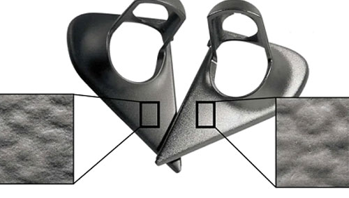
Products with textured sides and those that are glossy are more prone to scratching.

The first thing a mold designer thinks of when a product has scratches on a textured surface is that the draft angle on the side of the product is not large enough. However, why do scratches frequently persist even after the draft angle is increased? Therefore, preventing scratches requires more than just adjusting the draft angle. Actually, it's not at all that easy.

The Causes of surface scratches mainly include the following factors:

Draft Angle

The key issue with the product is that the draft angle of the product is too small, resulting in scratches on the side of the product.

Mold Design

  1. Mold Structure: Improper mold matching design will also cause the core and the cavity to be misaligned during the mold opening process, thus causing product scratches.
  2. Design of the mold gate: The gate should be as far away as possible from the textured side surface, because the pressure at the gate is high also with a long pressure holding time, so the high clamping force will make the product to be prone to scratches.
  3. The product sticks to the mold cavity: We must ensure that the product 100% sticks to the mold core when the mold is open. If it sticks to the mold cavity, local product warpage may be caused, and thus scratches on the side surface.

Mold Machining

  1. Although the draft angle is designed to be big enough, it is difficult to measured accurately. It have to be taken into consideration.
  2. The mold polishing workload close to the bottom is higher and the one close to the parting surface is lower, which reducing the draft angle of the product, so it is also possible to cause product scratches.

Molding Machine Adjustment

  1. Excessive injection pressure and holding pressure
  2. Excessive material temperature
  3. Insufficient product cooling
  4. The bulging of the parting surface
  5. The cavity texture surface have to be kept clean.
  6. The injection molding machine is aginged- no parallelism between the front and rear plates or vibrations.

11. Crack

Crack

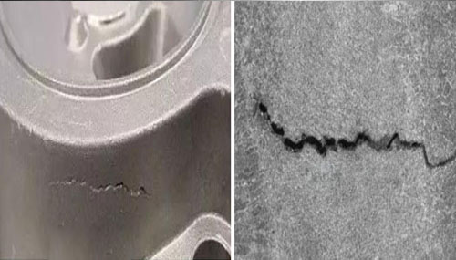
Crack is a common flaw in products made of plastic; it is primarily distinguished by cracking in areas of high stress, such as near the welding joint, or by paint cracking after prolonged coating. Stress deformation, specifically the deformation brought on by residual stress, external stress, and stresses from the external environment, is the main cause of this problem.

Sources of defect:

Material/ Granulate

  • Plastic material overdried

Plasticising:

  • Melt temperature too low
  • Holding pressure too high (no holding pressure profile used)

Injection:

  • Injection speed too fast/ slow

Cooling:

  • Cavity temperature too low

Mould:

  • Demoulding with high force

12. Ejecting Mark

Ejecting Mark

The ejector pin frequently leaves deep or shallow traces on the plastic part after it is ejected from the mold. These traces could be far enough from the product face and shallow enough. Then it is safe to disregard them. However, these marks can be problematic if they leave asymmetric, deep, and non-uniform marks on the surface of the part. Even though it might be tempting to assume that ejector pin marks are exclusively the result of the part adhering to the mold and that this makes them a mold problem, the truth is that they are more closely related to the manufacturing procedure. Visible ejector marks are what are left behind when these traces grow too large. The ejector site can be elevated above the part surface in the worst-case scenarios.

Sources of defect:

Material/ Granulate

  • Plastic material overdried

Plasticising:

  • Melt temperature too low
  • Holding pressure too high (no holding pressure profile used)

Injection:

  • Ejection speed too fast
  • Excessive injection pressure or holding time
  • Terminal injection speed too fast

Mould:

  • The mold temperature is too low or too high
  • Draft angle too small
  • Unbalanced runner system
  • The ejector pin is not in sufficient quantity or position
  • Air trapped in mold
  • Thin walls where the ejector pin marks appear
  • The ejector pin size is too small or the ejection speed is too fast

13. Flaking

Flaking

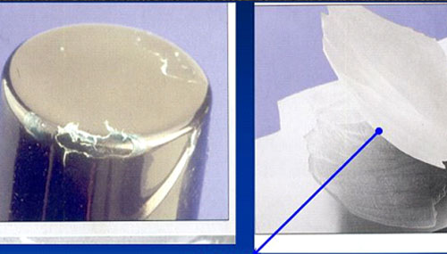
The surface layer of a moulded part will flake off if the individual layers do not properly bond together. High share forces between the layers of the moulded part, inhomogeneities in the melt, or foreign material can all contribute to this.

Sources of defect:

Material/ Granulate

  • Plastic material soiled or contaminated with foreign material
  • Granulate soiled or contaminated with foreign material
  • The masterbatch is not compatible with base material
  • Colour dosage is too high

Plasticising:

  • Melt temperature too low
  • Back pressure too high
  • Screw speed too high

Injection:

  • Injection speed too high

Mould:

  • Dead spots in the hot runner

Machine:

  • Dead spots (washouts) in the plastification unit
  • The plastification unit is dirty

14. Cold Slug

Cold Slug

If the plastic is not completely melted or has cooled down in the nozzle, unmelted plastic is injected. If this cold slug divides the melt flow, an additional weld line is created in the moulded part.

Sources of defect:

Plasticising:

  • Melt temperature too low
  • Nozzle temperature too low
  • Decompression too low

Mould:

  • Too much cooling of the sprue bush
  • Insulating cap is missing from the hot runner nozzle
  • No cold slug well available

Cooling:

  • Mold temperature too low
  • Plasticising unit lifts off to late

Machine:

  • Nozzle hole is too small
  • Nozzle temperature control (nozzle band heater) defective
  • No shut-off nozzle in use
  • Dwell time in the cylinder too short

15. Burn Marks

Burn Marks

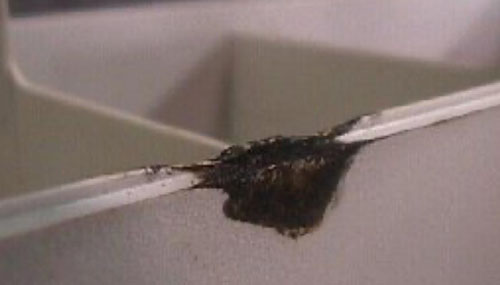
When air, other gases, or disintegrated materials are trapped inside a part, they cause it to overheat, resulting in air burns, which appear as black and brown marks or silver streaks. This may result in burn marks, short shots, a lack luster surface finish, or diminished mechanical properties of the molded part due to thermal degradation of the plastic material.

To let these gases out and, in the process, maintain the melt's temperature, proper venting is necessary. The right number and width of channels, as well as a slower, more consistent injection, will determine venting. The slight yellowing of white pellets' color is a more subdued but more frequent problem.

Sources of defect:

Material/ Granulate:

  • Excessive melting temperature (viscosity reduction)
  • Drying temperature is too high
  • Drying time is too long
  • Additives too thermally sensitive
  • Grit size too different (granulated) or (regrind content)
  • Brown/ black dots in the granulate

Plasticising:

  • Melt temperature too high
  • Dosing speed too high
  • Back pressure too high
  • Residual melt cushion too big

Injection:

  • Injection speed is too high
  • Injection pressure too high

Cooling:

  • Mold temperature too low

Mould:

  • Hot runner temperature too hot
  • Dead zones in the hot runner
  • Sharp edged transitions
  • Flow cross sections too small
  • Poor mold venting
  • The gate is too small or in the wrong place
  • Excessive clamping force (the vent becomes smaller)
  • The vent or is blocked

Machine:

  • Nozzle hole is too small
  • Plasticising unit too large / dwell time too long
  • Dead spots in the plasticising unit
  • Dead spots in the shut-off nozzle
  • Nozzle does not seal properly on the to the mold
  • Heater band/ thermocouple defective

Part design:

  • Sharp edged deflections
  • Sudden change in wall thickness from think to thick

16. Jetting

Jetting

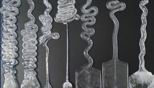
The surface of the parts (in front of the edge gate) will produce a serpent- shaped line if the melt is injected at the gate too quickly. Jetting is a common name for this. Edge gates are primarily where jetting happens. The plastic melt suddenly enters the open, relatively wide areas of the mold after flowing quickly through the nozzle, runner, gate, and other narrow areas. Here, it will bend forward along the flow direction like a snake. After making contact with the mold surface, the molten plastic will then quickly cool. This phenomenon leads to a visual defect because the first piece of material to enter the cavity can't have good fusion with the rest of the resin entering the cavity later.

Sources of defect:

Material/ Granulate:

  • Plastic material has very high viscosity
  • The material temperature or mold temperature is too high

Plasticising:

  • Melt temperature too low

Injection:

  • Injection speed is too fast (in gate)
  • No injection profile used

Cooling:

  • Mold temperature too low

Mould:

  • Changeover from gate to moulded part not rounded
  • Unfavourable sprue position
  • Gate diameter too small
  • Improper placement of gate (Direct injection into the cavity)

Machine:

  • Nozzle hole is too small

Part design:

  • Sharp edged deflections
  • Sudden change in wall thickness from think to thick

17. Gate Blush

Gate Blush

If the gate is too small and the injection speed is too fast, the melt flows violently and pulls air into the melt. This will leave cloudy marks in the gate location, turning points, and step positions of the plastic parts. It’s easiest to see gate blush at the gate with materials like ABS, PC, and PPO.

Sources of defect:

Material/ Granulate:

  • Plastic material has very high viscosity and the fluidity is poor
  • The material temperature is too high or the mold temperature is too low
  • Raw materials are not fully dried or are decomposed by overheating

Injection:

  • Injection speed is too fast

Mould:

  • The gate is too small or improperly positioned
  • Excessively long or thin runners (melt is easy to cool)
  • Air trapped within mold due to bad vent
  • The cooling channel is too small or insufficient
  • Can’t figure out maximum injection temperature required with the current mold setup

18. Colour differences

Colour differences

It is very common for color differences to occur when changing work from one mold to another on the same injection molding machine.

Sources of defect:

Material/ Granulate:

  • Different drying
  • Batch of the material
  • Batch of the pigments
  • Different colour dosage

Plasticising:

  • Different backpressure
  • Different melt temperature
  • Different dosing speed
  • Different residual melt cushion

Injection:

  • Different Injection speed

Machine:

  • Different machine nozzle

Peripherals:

  • Different colour dosing system in use
  • Different settings on the colour dosing system
  • Different hot runner controllers in use
  • Different thermos-lines

19. Drag Marks

Drag Marks

When your part has scratches or gouges in its surface, this may be a sign that the part is dragging against the mold cavity walls as it is being ejected. This can happen when the draft angle is insufficient to accommodate shrinkage and ejection or the mold’s surface finish is perpendicular to the release direction.

This often means that a redesign and adjustment to the part and mold must be made to increase the draft angle or change the position of the parting line.

Sources of defect:

Mould:

  • Flashing on the side of the mold cavity
  • Draft angle is not enough
  • The inner side of the cavity is too rough
  • Excessive clamping force (mold cavity deformation)
  • Front mold temperature is too high or cooling time is not enough
  • The mold opens too quickly
  • Mold locking end too fast (mold cavity impact collapse)
  • Excessive injection pressure or hold-in duration

20. Tiger Stripes

Tiger Stripes

The melt front may flow unevenly during the injection process or the source flow may break through. On the component surface, over a larger area, tiger stripes cycle in and out. The formation of flaws is facilitated by a smooth mould surface.

Tiger stripes frequently appear in high viscosity materials, primarily TPE, PP, and PE.

Sources of defect:

Material/ Granulate:

  • Drying temperature too high
  • Drying time too long
  • High viscosity material
  • Sliding aid and demoulding aid too thermally sensitive
  • Wax / paraffin content too high
  • Integration of aggregates insufficient

Plasticising:

  • Cylinder temperature too low
  • Cylinder temperature too high
  • Backpressure too low
  • Dosing speed too high
  • Dwell time too long
  • Dwell time too short

Injection:

  • Injection speed too high
  • Injection speed too low

Cooling:

  • Mold temperature is too high
  • Cooling time too short

Mould:

  • Cross section of gate too big, too little shear (TPE)
  • Flow path length too long
  • Cross section of gate too small, shear too high

Machine:

  • No sufficient homogenisation
  • Nozzle hole is too small

Part design:

  • Unfavourable flow path to wall thickness ratio

21. Vacuum Voids/ Blow Holes (Vacuoles)

Vacuum Voids/ Blow Holes (Vacuoles)

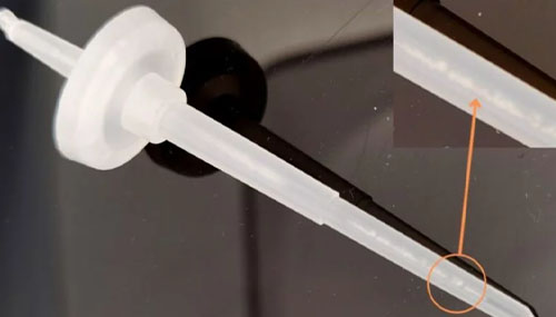
Shrinkage in the interior of a plastic part is often called a vacuum void. It is generally found in an area where the plastic is very thick or where multiple channels come together to form a rib or a wall. These areas are especially susceptible to uneven cooling or shrinking, which is the underlying cause of voids.

When the part is cooling down after the injection is completed, areas of thicker plastic will tend to dry at a different rate than thin ones. If the hardness of the plastic isn’t high enough or there isn’t enough fiber mixed into the raw material, voids can form within the plastic as it shrinks unevenly. What separates bubbles from vacuum voids is the lack of air. A simple heating test can reveal the exact issue. A vacuum void will create a debris while a bubble would burst outwards.

Sources of defect:

Material/ Granulate:

  • Plastic has too much shrinkage
  • Flow rate at the temperature control unit too low

Plasticising:

  • Residual melt cushion too small
  • Holding pressure too low
  • Holding pressure time too short
  • Changeover point too early

Injection:

  • Injection speed too high
  • Injection volume too low

Cooling:

  • Mold temperature is too high

Mould:

  • Sprue and gate too small
  • Gate in an unfavourable position
  • Flow paths too long
  • Temperature regulation inadequately designed

Machine:

  • Non return valve worn out
  • Nozzle hole is too small

Part design:

  • Wall thickness differences on the moulded part are too big
  • Melt accumulation e.g. due to ribs or screw eyes

22. Black Specs/ Dots

Black Specs/ Dots

Black specks frequently appear on plastic parts that are transparent, white, or light-colored during the injection molding process. The black specks on the plastic parts' surface can reduce the aesthetic quality of products, leading to a high rate of product rejection, waste, and high production costs.

Injection molding makes it difficult to avoid the issue of black specs, so it is necessary to control the raw material, crushed material, ingredients, feeding, environment, and production processes to lower the spec rate. The primary cause of the black impurities is the degradation of the foreign material within the plastic melt at high temperatures.

Sources of defect:

Material/ Granulate:

  • The raw material is mixed with foreign matter or the drying bucket is not cleaned
  • Impure or contaminated water outlet
  • Colour pigment diffusion is poor, resulting in condensation point
  • Conveying speed material is too high
  • Machine hopper not cleaned
  • Black dots already compounded into the delivered granulates
  • Wall sticking material on the screw

Plasticising:

  • Melt temperature is too high
  • Dosing speed too high
  • Backpressure time too high
  • Backpressure too low
  • Dwell time too long
  • Debris in the barrel causes the material superheated decomposition
  • The nozzle is blocked or the nozzle tip is too small
  • Crusher/mixer not cleaned up

Mould:

  • Wall sticking material in hot runner
  • ‘Dead spots’ in the hot runner at corners or e.g. pin fits
  • An injection unit that is too large leads to long dwell times of the melt in the unit

Machine:

  • ‘Dead spots’ on the valve gate of the machine nozzle
  • ‘Dead spots’ on shear and mixing screws
  • Damaged surface on the screw
  • Flanks of the screw dirty

23. Black Clouds

Black Clouds

The dust content in the granulate melts faster than the granulate which causes thermal damage. If the granulate is dried for too long, it can also be damaged. If air is in the melt, it burns during injection. In all 3 cases dark, black clouds may appear in transparent plastic parts.

Sources of defect:

Material/ Granulate:

  • Dryer not cleaned
  • Dust content in material too high
  • Conveying speed material is too high
  • Machine hopper not cleaned
  • Black dots already compounded into the delivered granulate
  • Wall sticking material on the screw

Plasticising:

  • Melt temperature is too high
  • Dosing speed too high
  • Backpressure too low
  • Backpressure too high
  • Dwell time too long
  • Decompression too great
  • Decompression too fast

Mould:

  • Material sticking to the wall in the hot runner
  • ‘Dead corner’ in the hot runner at deflections or e.g. pin fits

Machine:

  • ‘Dead spots’ on the valve gate of the machine nozzle
  • An injection unit that is too large leads to long dwell times of the melt in the unit
  • ‘Dead spots’ on shear and mixing screws
  • Damaged surface on the screw
  • Screw flanks dirty

24. Glossy Difference

Glossy Difference

The finished surface of the plastic part can become fuzzy or lose its original luster during the molding process. It may also form an opalescent film.

The surface condition of the mold is primarily to blame for the variations in surface gloss between plastic parts. The finished product's surface won't have a good gloss if the mold's surface is not well-polished or contains mold scale. Poor surface gloss can also be brought on by the excessive use of release agents or oil release agents. Gloss differences may also result from the material being hygroscopic or from the material having volatile or foreign substances (pollution) mixed in.

Sources of defect:

Material/ Granulate:

  • Excessive mold release agent in the mold
  • The raw material isn’t dry enough
  • Mold temperature or material temperature is too low

Plasticising:

  • The density of the melt is not enough or low back pressure
  • Insufficient holding time
  • The charge decomposes due to overheating or stays in the cylinder for too long
  • Material cools down prematurely due to small runner and gate size

Injection:

  • Injection speed is too slow or the mold temperature is uneven

Mould:

  • The surface of the mold is permeated with water or oil
  • The inner surface of the mold is not smooth
  • Mold cavity is scaly
  • Gates and gate cross-sections are too small